The ball spline is an innovative linear motion system that simultaneously provides low-friction linear sliding motion and high-efficiency torque transmission through precision recirculating bearing balls. Unlike traditional friction splines, a ball spline achieves zero rotational backlash and superior rigidity using a single preloaded nut.
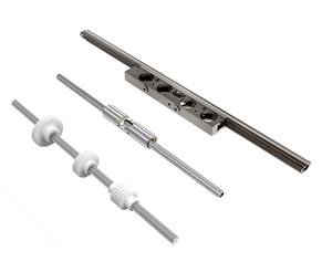
Figure 1: King Square Precision Ball Spline Shaft and Flanged Nut Assembly
1. Fundamental Operating Principles
The ball spline consists of a precision-ground spline shaft with gothic-arch raceway grooves, a spline nut containing recirculating ball circuits, and precision steel balls:
- Gothic Arch Contact: Steel balls contact raceways at a calibrated contact angle, transmitting large bidirectional torque while permitting smooth axial reciprocating motion.
- Compact Single Nut Design: By adjusting steel ball diameters or implementing angular contact offsets, a single nut achieves zero rotational clearance without adding axial length.
- Rolling vs Sliding: Converts sliding friction into rolling motion, reducing the friction coefficient to less than 0.003 and eliminating stick-slip at low velocities.
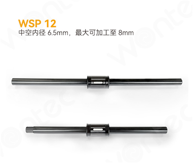
Figure 2: Recirculating Ball Path and Gothic Arch Raceways Cross-Section
2. Accuracy Grades and Tolerances
King Square ball splines are manufactured in three standard accuracy grades defined by JIS/ISO standards:
- General Grade (G): Suitable for general automation transfer mechanisms and material handling.
- High Grade (H): Standard for automated assembly machines, packaging, and semiconductor handling stages.
- Precision Grade (P): Ground spline shafts for high-precision SCARA robot Z/theta axes and medical diagnostic analyzers.
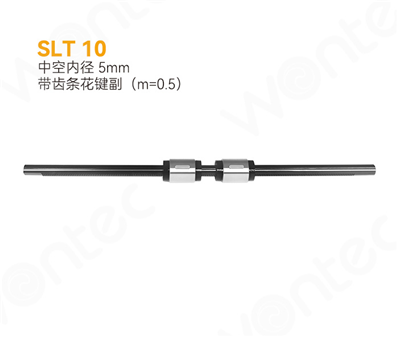
Figure 3: Ball Spline Dynamic / Static Load Capacity and Runout Tolerances
3. Preload Classes
Selecting the appropriate preload class depends on operational rigidity and positioning precision requirements:
| Preload Class |
Clearance / Preload Range |
Operating Conditions & Applications |
| Standard Clearance (0) |
0 to +4 μm |
Low vibration, smooth manual movement, vertical guide pins. |
| Light Preload (T1) |
0 to -2 μm (0.02 C) |
Overhanging loads, moderate rotational torque, SCARA robots. |
| Medium Preload (T2) |
-2 to -6 μm (0.05 C) |
High rigidity, strong shock loads, high-speed reversing cycles. |
4. Mounting and Handling Precautions
- Do Not Disassemble Nut from Shaft: Never remove the spline nut without inserting a dedicated plastic dummy sleeve; otherwise, internal balls will dislodge.
- Avoid Over-Torque on Retaining Screws: Tighten nut flange screws symmetrically using calibrated torque wrenches to prevent raceway deformation.
- Shaft Chamfer: Always machine an introductory chamfer (15° to 20°) and deburr shaft ends when installing support bearings.